Go-NoGo gauge design
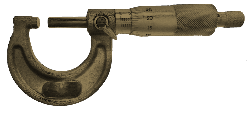
Go-NoGo gauges are a good tool for speeding up your inspection on production items. Instead of spending 10 minutes measuring points with a micrometer and checking if that’s within your tolerance band, you can simply insert a go gauge, check it “goes,” check you can’t insert the “no go” and you’re done.
What they are
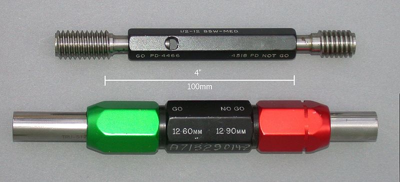
Go-NoGo gauges are a pair of gauges. The “Go” gauge should fit into the part and checks it is not exceeding its Maximum Material Condition. The “NoGo” gauge should not fit and checks the Minimum Material Condition. Below, there’s a photo of a thread go-nogo gauge and a pin go-nogo gauge below it.
Tolerance calculation
Your part will have tolerances of course but so will your gauge. Because your gauge has tolerances, you will have some percentage of false rejects. Why false rejects and not false passes? Because we intentionally design it that way. A false pass sends a defective part out the door. A false reject can be verified and confirmed using a more accurate (and slower) measurement technique.
A common rule of thumb I’ve seen on the internet is that the gauge should be about 1/10th the tolerance that you have on your part. But rather than just accept this, let’s do some calcs and see what really happens. Take a shaft that is to be made 30.00mm to 30.20mm. If you could make a perfect go-nogo gauge that didn’t wear, the go gauge would be a hole of diameter 30.20mm and the nogo would be 30.00mm (the exact shape of this will be discussed more later.
We add a small amount for wear allowance, say, 0.002 on the go gauge only (the go gauge shouldn’t be go-ing so much as to wear significantly), and assume your manufacturing tolerance of the gauge itself is +/- 0.01. Your go gauge should then be specified 30.20 – 0.002 – 0.01 = 30.188 and with its +/-0.01 tolerance will come out somewhere between 30.178 and 30.198.
Conversely, your nogo gauge should be 30.00+0.10 = 30.010 and with its +/-0.01 tolerance will come out somewhere between 30.00 and 30.02. Here’s a table to make it easier- note it assumes a male part and female gauge:
| Minimum dimension | Maximum dimension | |
| Part | 30.00 | 30.20 |
| Go gauge | 30.178 | 30.198 |
| Nogo Gauge | 30.00 | 30.02 |
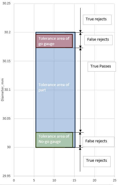
Here’s a graphical depiction:
Calculating reject rates
So now we have a set of tolerances for our gauges that deliberately biases it to avoid incorrectly passing a part that is out of spec at the expense of falsely rejecting some parts that are near the edge of tolerance. If the manufactured part’s tolerances were linearly spread across the sample space, you would then expect this gauge to falsely reject 21% of parts but in reality, the tolerance of the parts will follow some form of normal distribution. Here’s the same chart again but this time, I’ve overlaid a bell curve with a standard deviation of 0.02 which is very easily achievable by a modern CNC machine to show the probability density of the sizes.
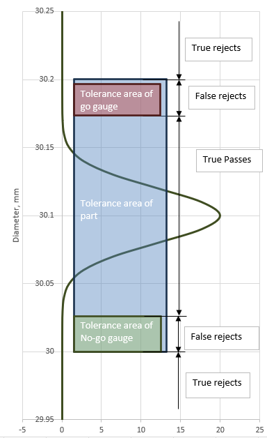
If we assume a normal distribution and make a reasonable estimate for our standard deviation, the false reject rate can be calculated based on that. In our case above, it works out to be about 0.005% (you can use Excel’s =NORM.DIST function for this). In fact, the number of true rejects is 0.00001% (It’s pretty hard to miss a 0.2mm tolerance with a CNC lathe with 0.02mm std deviation). Because our part has a loose tolerance, we don’t need to make a particularly fine gauge to get such a low percentage of false rejects.
Let’s see what happens now with a tighter part tolerance. 30mm +0.05 -0.00 with the exact same gauge results in 33% false rejects and 21% true rejects. For most applications, it would be a good idea to talk to your supplier and see if they can go a bit finer on the tolerance of the gauges. Changing the gauge tolerance to +/- 0.005mm will result in a significantly more expensive gauge but your expected false rejects is now only 15%. Reducing the wear allowance on the go gauge drops this down again to 14%.
Shapes
Ideally, go gauges should check all inspection features at once and nogo gauges should check them individually. This avoids false passes. To understand why, imagine our shaft again. It’s 30mm diameter and 100mm long. It’s also undersized and bent like a banana. Our go and nogo gauges are both a bore the same length of the part. It easily goes in the go gauge because it’s undersized and it doesn’t go in the no-go gauge because it’s bent like a banana. So we pass the part and make a customer angry.
The way to get around the problem in this case is to leave the go gauge alone and make the no-go gauge a thin “C” shape so you can check the diameter of the shaft in a couple of locations along its length. This would reject the part successfully.

Wear allowance
I very quickly skipped over wear allowance earlier and just tacked on 0.002mm. This number came from a bit of google searching and some intuition. I went on a machine scraping course some time ago and each scraping pass took about that much material off a cast iron block using a carbide tool and light force. It seems like a reasonable number. Given that some gauges will be made of quite fine tolerances, wear allowances can get pretty small and this highlights the need to periodically check the calibration of your tools.
Temperature and storage
If your gauges are getting to be very fine in tolerance, it may begin to matter what temperature they are. The gauge described above may grow as much as 0.007mm if it’s made from aluminium, calibrated at 20 degrees C and used at 30. About half that if it’s steel. As a general rule, if the thermal expansion from holding a part in your hand is a significant concern and you aren’t in the aerospace, metrology or nuclear industry, it’s time to stop and make sure you are going down the right path. Also, a dirty, chipped and corroded gauge won’t be of much use so if you are making one, think about how you plan to store it.
Final words
You should now be able to design your gauges with some confidence. Remember that a gauge is only as good as the person using it. Take care to do your own calculations and don’t treat my assumptions (particularly standard deviation) as gospel- Think carefully. Have fun and may your inspections be fast and accurate.
Are there any benefits to using a specific material for your gauges other than preventing wear? For example, is it desirable in any way to use the same material for your gauges as the parts you are fitting? Or perhaps you would want a material with a lower or higher coefficient of friction or thermal expansion for some reason? – PS your new website is awesome and the blogs are great! – An old apprentice.
Hi Shaun, great to hear from you again!
That’s a good question. The thermal expansion of the part and gauge match each other but only if they are at the same temperature. If they are dissimilar metals they both need to be at the temperature they were calibrated for. At the point that you are temperature controlling though, a gauge like this probably isn’t appropriate anymore. A change in size of 7 microns doesn’t make a part go from “easy fit” to “clearly won’t fit,” It’s more likely going to go from “kinda feels like it’ll go but I’ll have to force it” to “might go maybe if I force it.”
I’m open to being corrected on this but for most applications, I don’t think there’s much to be gained from deliberately going for similar materials between gauge and workpiece for reasons of thermal expansion.
In most cases, I’d just make it out of stainless if I was more worried about corrosion or carbon steel if I was more worried about thermal expansion or galling.