Design tips for CNC milled parts
If you have designed a part to be CNC machined before then you have almost certainly spoken to a machinist about how to make your impossible part. I certainly have. In fact, I’ve even found myself saying “why the hell did I do that” when machining my own drawings. Here’s a few pointers that I’ve picked up over the years.
Tool setups
Setting up tools on CNC machines takes longer than you’d expect. After checking, cleaning and installing the tool in the tool holder and installing the tool holder in the machine, you then have to set up the tool parameters in the machine, including the tool offset which generally involves slowly indexing the tool into a probe so the machine can know its exact position. When I was learning to use CNC machines at TAFE in Australia, it would take me at best 10 minutes per tool. A good machinist would of course be much faster than this but there is no magic and the process must be followed.
CNC machines also have a limited number of tool holders that can be set up simultaneously. For example, this DMG holds 30 and this Okuma holds 20. Machine shops will typically have the common sizes installed already from whatever jobs came previously- a couple of roughing end mills, a couple of fine end mills, some common drills and taps, face mills, thread mills, etc. You can image that 20 or 30 tool slots gets used up pretty quick so every job will likely have a few tool changes and setups. We want to avoid having too many though.
So having said all that, if your part requires every size end mill to make, the machinist will have quite a bit of setup to do and this makes your parts expensive. When you’re designing parts and your mouse is hovering over the “Fillet” feature, think about what fillet sizes you already have on your part.
Corner Radii
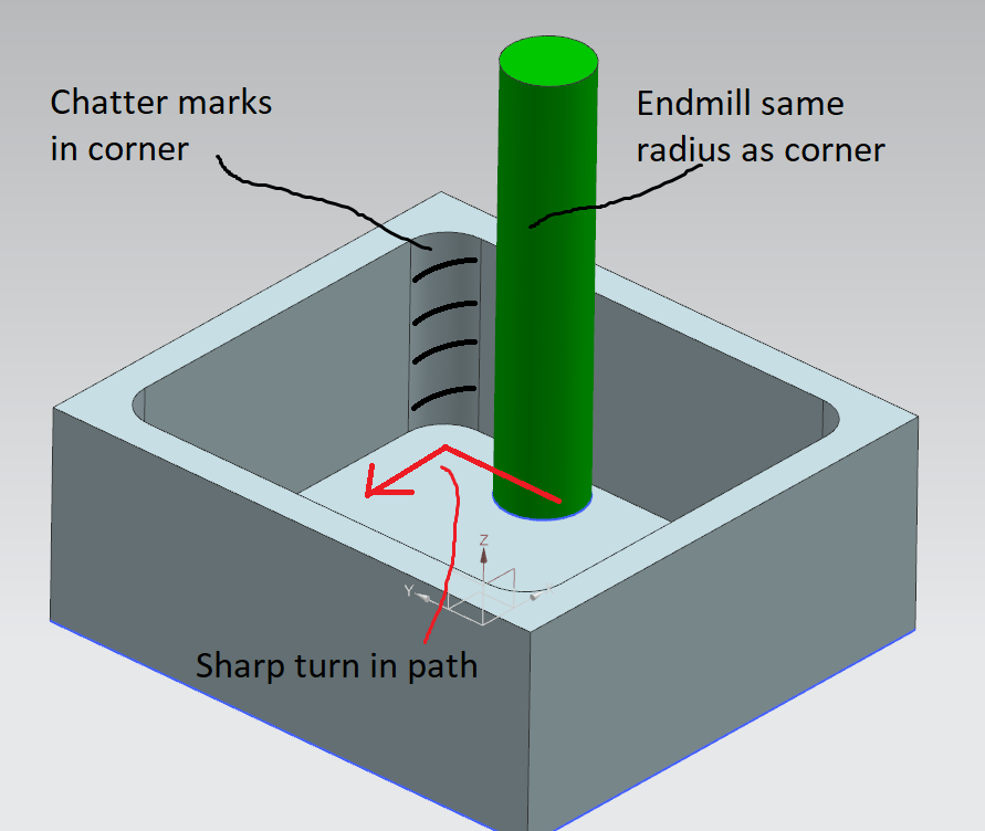
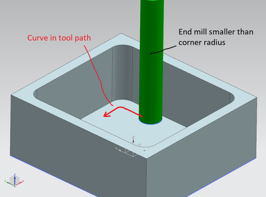
Another point on radii- if you are machining a 5mm wall radius with a 10mm cutter, the machine needs to do a straight line cut, stop and change direction 90 degrees and then continue on. During that direction change, the machine will “dwell” for just a fraction of a second in the corner with no cutting forces to dampen its vibration and this causes a chatter mark right in the corner. You can mitigate this quite a lot by having that radius just slightly larger than the cutter size you intend to use. So, for example, having a 5.2mm radius to be cut with a 10mm end mill.
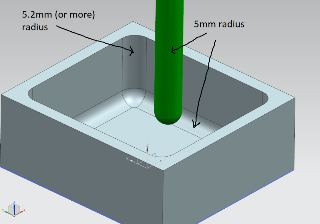
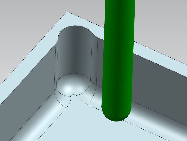
Note that this trick applies to the wall corner only. If you have a corner radius on the bottom face, you want to match that to the radius of the cutting tool- otherwise the machine will have to do multiple passes to get the correct radius- See image below. For this example, I’ve drawn a box with a 5.2mm radius on the wall corner to be cut by a 10mm diameter (5.0mm radius) ball nose end mill. The radius between the wall and the floor, I’ve kept at 5mm.
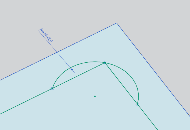
Sometimes having a large radius won’t work for your design. In this circumstance, rather than trying to actually make a sharp internal corner, which would require broaching, EDM or some form of magic, we design an undercut. My preferred method of doing this is shown below. I sketch in an arc and constrain it to the corner point. I then apply a fillet to the intersection corners.
Chatter
Chatter is most commonly caused by vibration of either the tool or the workpiece. It leaves unsightly helical marks in your part, it shortens tool life, it shortens machine life and it makes an annoying sound. Since it’s been a thorn in the side of all machinists since forever, most machines have already taken the obvious steps to mitigate it- Carbide tooling, rigid machine spindles, fast spindle speeds and rigid work-holding to name a few. There’s some not-so obvious ones, too like trochoidal cutting paths, left hand spiral end mills and coolant driven high speed spindles. But none of these can stop a a super thin wall or an extremely deep cut with a small diameter cutter from causing problems.
There’s no universal rule on how thin is too thin but I personally avoid going thinner than 2mm wall thickness and deeper than the length of a standard end mill. This is extremely conservative- You can definitely push further than this but check with your machine shop first.
Work holding
As with mitigating chatter, there’s a whole lot of ways of holding on to a difficult-to-hold part, like Mitee bites, vacuum tables and so on. But you can save a lot of effort by just having two flat faces somewhere so the part can be clamped in a vice or some convenient bolt holes so it can be bolted down or held with expansion pins.
That’s all for today. I’m currently on holiday so keeping it short. Have fun and keep your machinist happy.