Laser cutting design tips
Laser cutting has been around for a long time and has been embraced by industry for the most part but I still do see some instances of designs that don’t really take advantage of all the things you can do with it. So I’ve come up with a list of a few tricks I’ve learned that you can do to save time, money and manufacturing effort.
One of the first big time savers I learned with laser cutting is the relative ease with which you can cut a thin rectangular hole in a part to correspond with a tongue on another part. Not only does it eliminate the need to measure out the position of the part but it also holds the parts together while they are being welded.
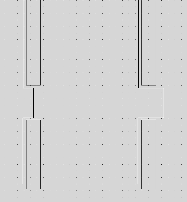
The clearance around the tongue should vary depending on the application and thickness but I’ve found that in 90% of situations (mild steel between 1mm and 10mm), a 0.25mm gap all around the tongue works. If you’re dealing with material over 10mm, you might want to increase this a little bit. Also, if you’re using obscure materials like high tensile, hard wearing or knife steels, you might find that the 6mm plate you thought you had is actually 6.35 (1/4″) so double check. The depth of the tongue is another parameter that requires a little thought. If you’re going to fillet weld the parts together and you have clearance on the back side of the slotted part, you can make the tongue long so it protrudes through (The example on the right in the below picture). A long tongue holds the part together better and makes assembly nice and easy. Alternatively, you might want to make the tongue short (half the part thickness) so that you can plug weld in the slot. (The left hand example). This results in a weld that can be ground flat without losing (much) strength.
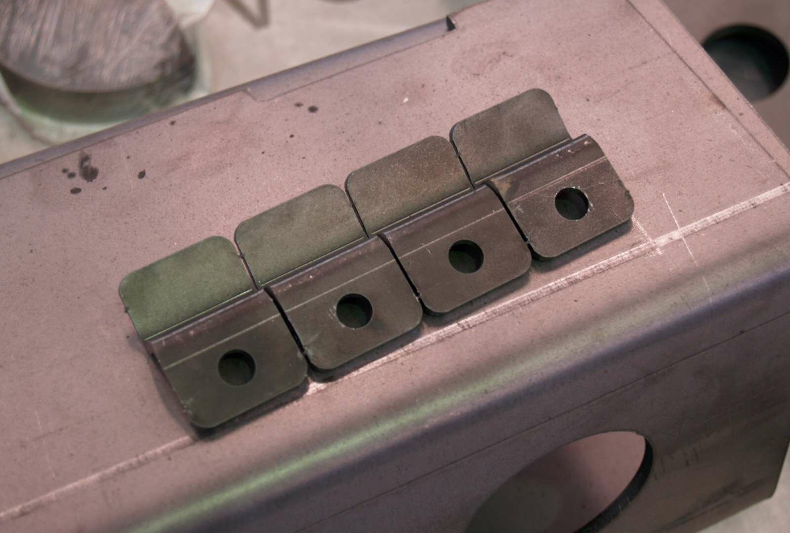
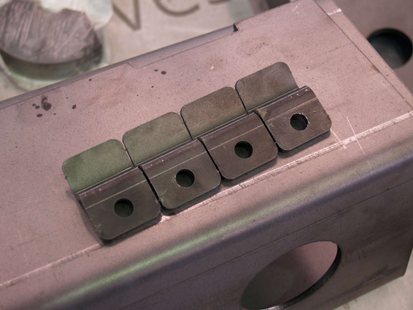
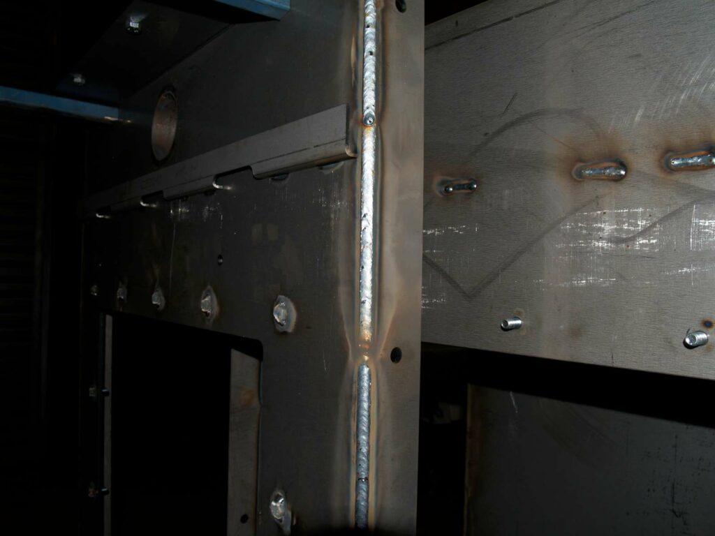
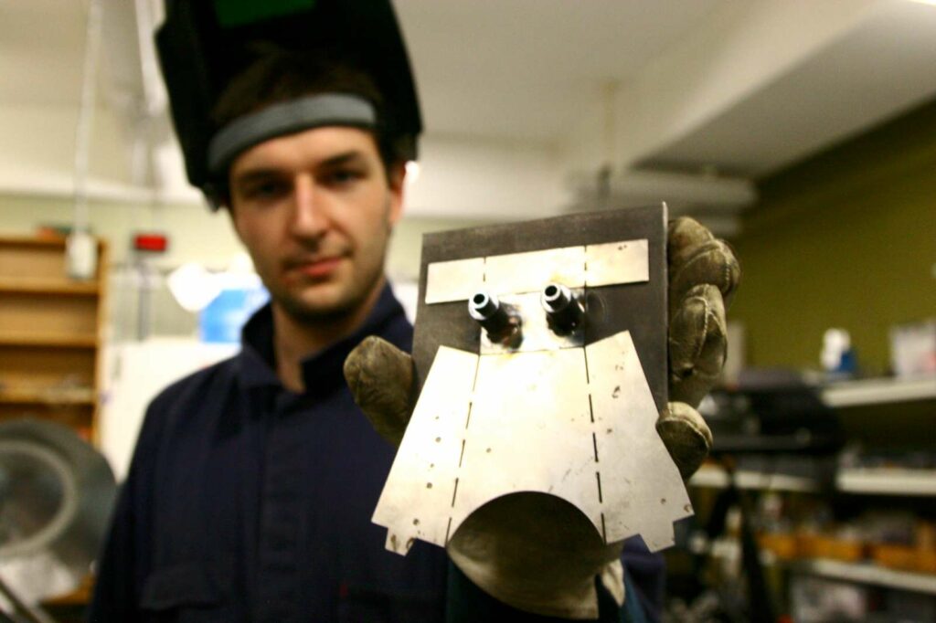
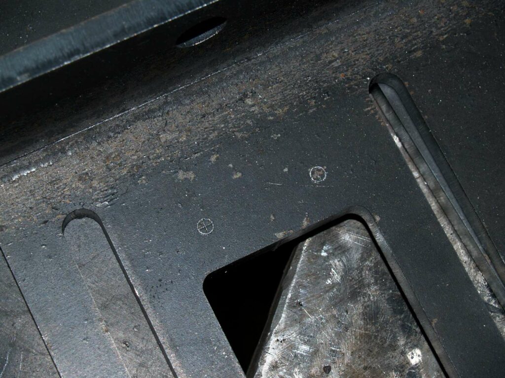
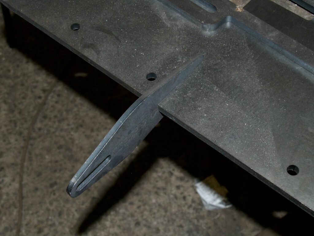
Below is a photo of a machine part with this trick done in 6mm thick mild steel. In the foreground you can see the bent part which has the tongues mated against the flat part that has the grooves cut into it. In the background, you can see the same assembly from the other side. Those lines of weld which are filled into the back of the groove.
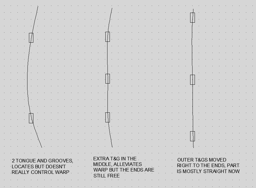
Another use for tongue and grooves is controlling warp. If you’re having long strips cut, you may find that they come back from the cutter with a significant bend in them. This can be alleviated with good design. See the picture below for an example. It’s a quick sketch showing a long warped piece with tongues cut in it being retained in a big sheet with grooves cut into it.
There are some pitfalls associated with doing this. The more obvious ones are the tongues and grooves just plain not lining up due to design changes in one part not following through to the other part or just not being the right size. This can be avoided by using the collision detection feature in CAD before sending out the drawings.
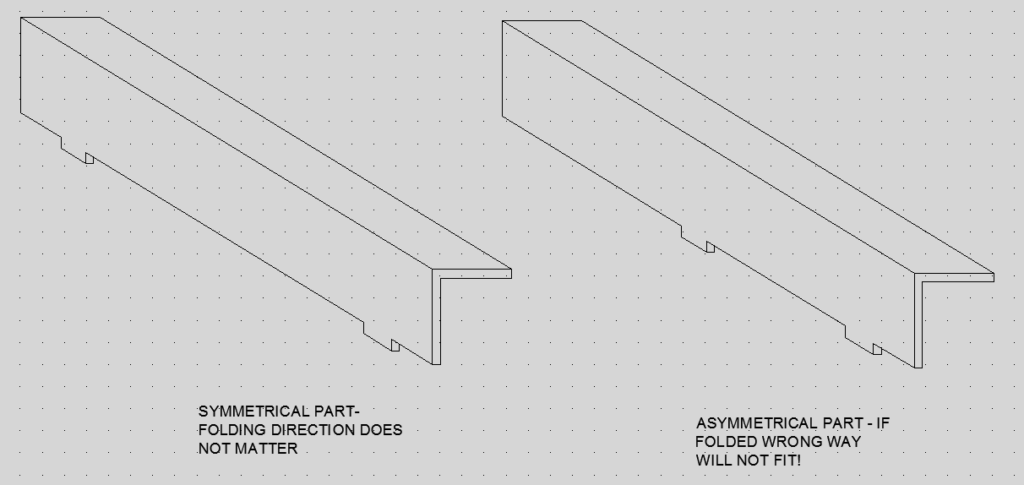
Some less obvious ways to screw this up occur when dealing with symmetrical or near-symmetrical parts. Below, a slightly asymmetrical part is shown with symmetrical tongues. It can be assembled either way. If you drawing is super clear, this may not cause any issues but a clear drawing and knowing you weren’t “technically” wrong is small consolation when you need to cut a machine apart to fix a mistake.
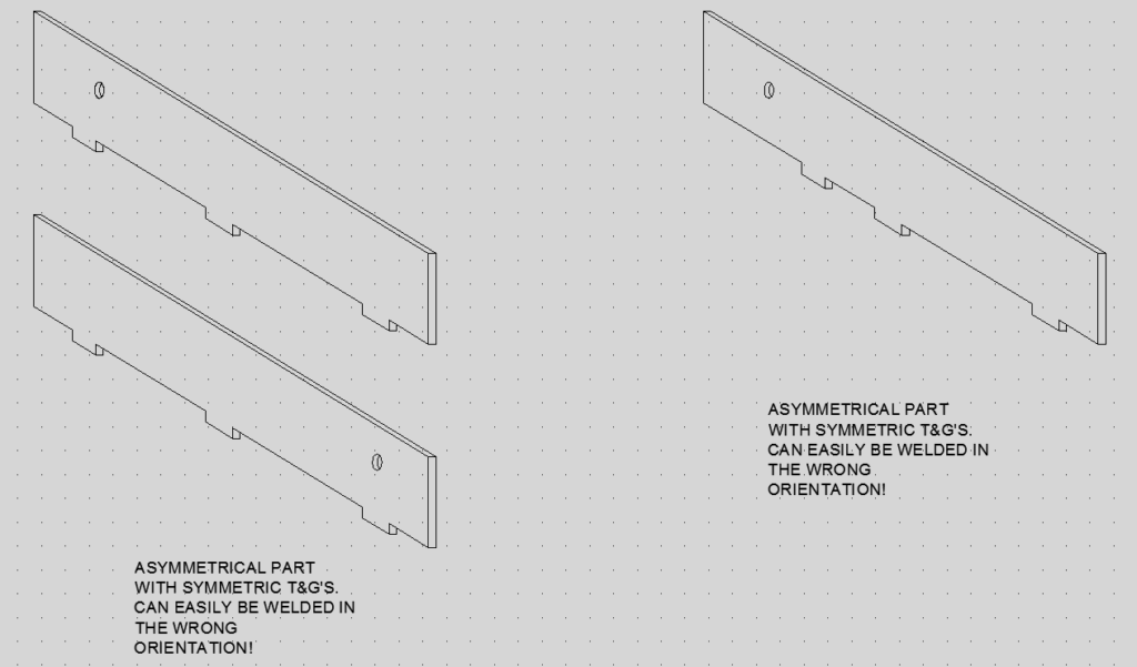
Incidentally, with the image above, another approach you can take is to make the part symmetric by mirroring that hole so that it doesn’t matter if the part is assembled the right way or not. Sometimes one way is better than the other. With CAD these days, it’s often easier to constrain your model so that the tongues and grooves are equispaced rather than to dimension them individually so I often find myself trying to preserve symmetry. Inevitably, though, a mounting hole is going to go in at the last minute and you may well forget to un-equispace those tongues and grooves. As such, I’m currently trying to get into the habit of making all of my tongue and grooves non-symmetric to avoid this happening.
Another pitfall arises when parts are being folded. Laser cutting is usually a 2D process, so the part you cut can usually be folded the “right” way or the “wrong” way, which would result in a mirror-image part. You can get around this by ensuring that the part is symmetric. Which brings us again to the conundrum I mentioned above- to symmetry or not? It’s very easy for your folder to misread a drawing and bend something the wrong way. I make an exception for folded parts. We’re engineers. We compromise.
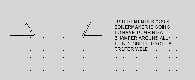
Sometimes you need to butt weld two parts together. This can happen because of limitations in the size of the sheet. Also, some laser cutters will quote material cost based on the smallest rectangle that can contain the part- so a very large “L” shape part made from two rectangular parts butt welded together can save you a lot of money when your material cost is high. In this case, you might want to cut dovetails into the part. If you’re just doing this to roughly locate the part then a 0.25mm clearance is fine. If you’re trying to use this to fully align the parts, though, you might want to cut that clearance down because you can get quite a large angular misalignment from a relatively small clearance. Also, bear in mind that your boilermaker is going to grind a chamfer all around that with an angle grinder (unless you do some trick 3rd axis laser cutting which is probably going to be too expensive) so it just might be cheaper in the long run to have a straight line joint and align the parts another way.
Depending on your method of manufacture, you may be able to avoid bending by cutting large slots out of your part, hand bending and then welding up the corners. In most industrial environments where you pay for both bending and welding this is definitely to be avoided however a “one man shop” may find good use for this technique.
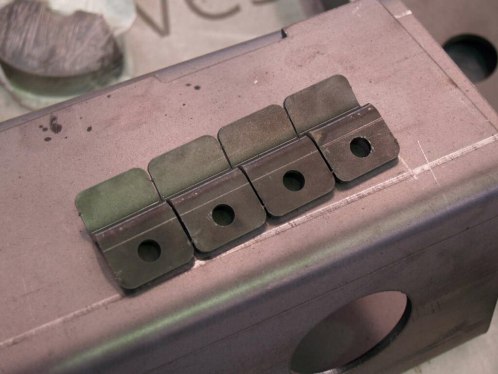
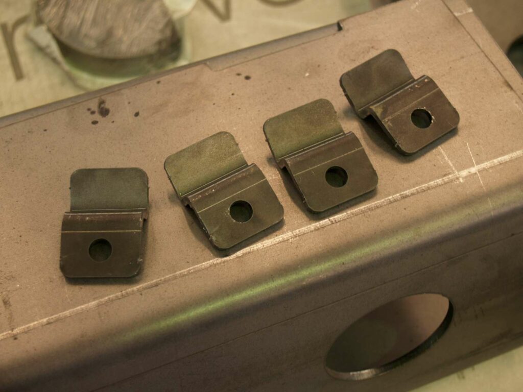
Another trick to reduce folding cost is shown below. If you look closely, there are small metal tabs holding these parts together. Some folders will charge per part without ammortising setup costs so sometimes it might be a good idea to join several parts together so they can all be folded in one hit and broken apart afterwards.
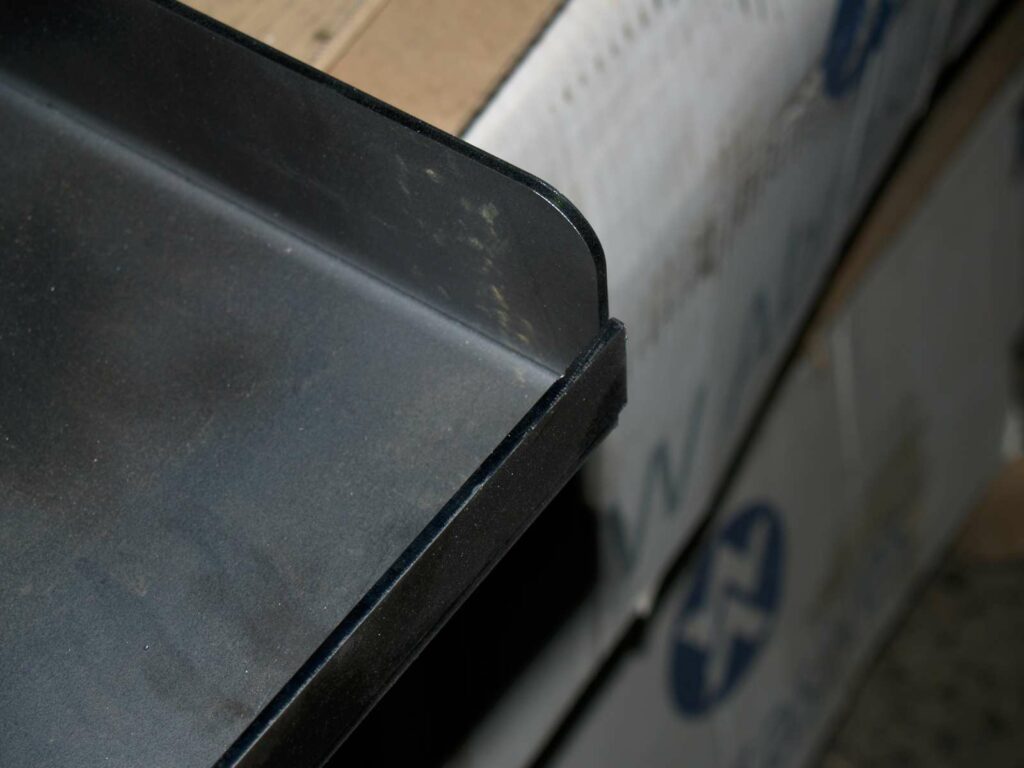
It used to be common practise for engineers to put a chamfer on every exposed corner so you don’t get a sharp edge that will cut or gouge unsuspecting operators. We used chamfers because they were easy to cut, grind, punch or shear. Nowadays it’s just as easy to laser cut a nice radius which looks a lot better.
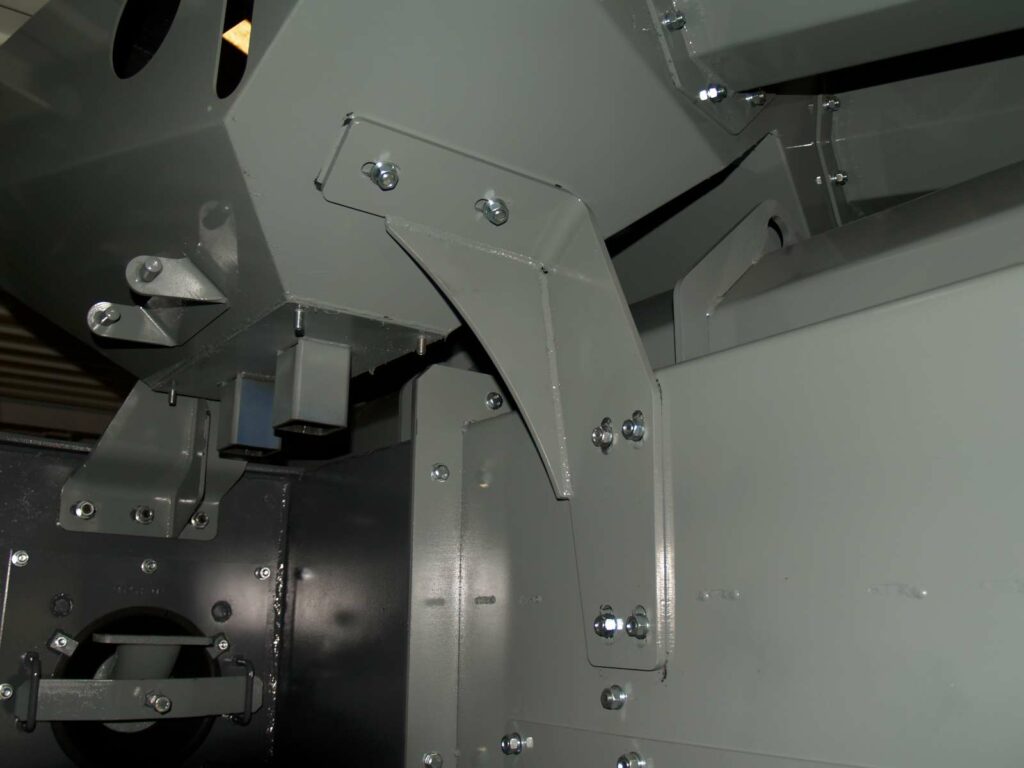
Below is a photo of am assembly where I was worried about tolerance stack. So I slotted the mounting holes to give myself some wiggle room. The part you can see is mounted by the slotted mounts you can see but is located by other, nonstructural parts (In this case, a pair of screw conveyor troughs on the upper right of the picture). Be careful with this- If position is important and your structure is not positively located in any way, putting slots in everything, everywhere will cause lots of confusion during assembly. Getting a few hundred kilos of steel in the right place with a crane and podgy bars is not easy.
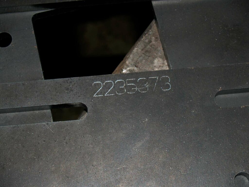
Most laser cutters can’t cut a hold that’s a smaller diameter than the sheet thickness so you’ll just have to drill it. Make it easy for yourself, though, and laser-etch the hole centre. Note, with modern pulsing techniques, laser cutters are getting better and better at small diameter penetrations though thick sheet metal so I don’t need to do this so often anymore.
Also, the cost added to etch on the part number is very little.
Another quick way of locating two parts:
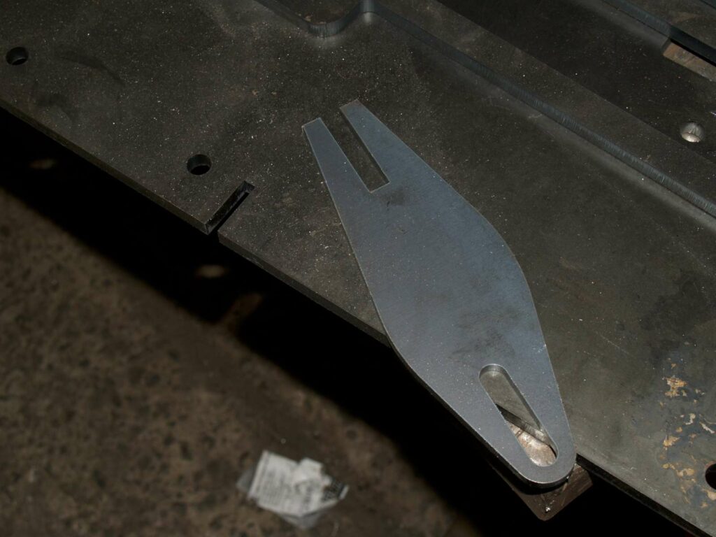
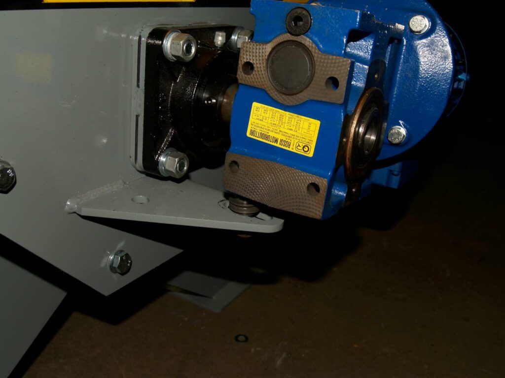
Slots aren’t just good for covering your potential mistakes. You can also use them to standardise your parts. Below is a photo of a standard torque arm. It’s slotted so that it will fit any size gearmotor.