Dust collector design
Dust collectors are a common off-the-shelf item and quite simple at first glance but interesting in detail and there are a few pitfalls in their design. In this article, I’ll discuss how to do some basic air flow calcs to help size them, describe in detail how they work and then cover a few design details and pitfalls.
Overall layout
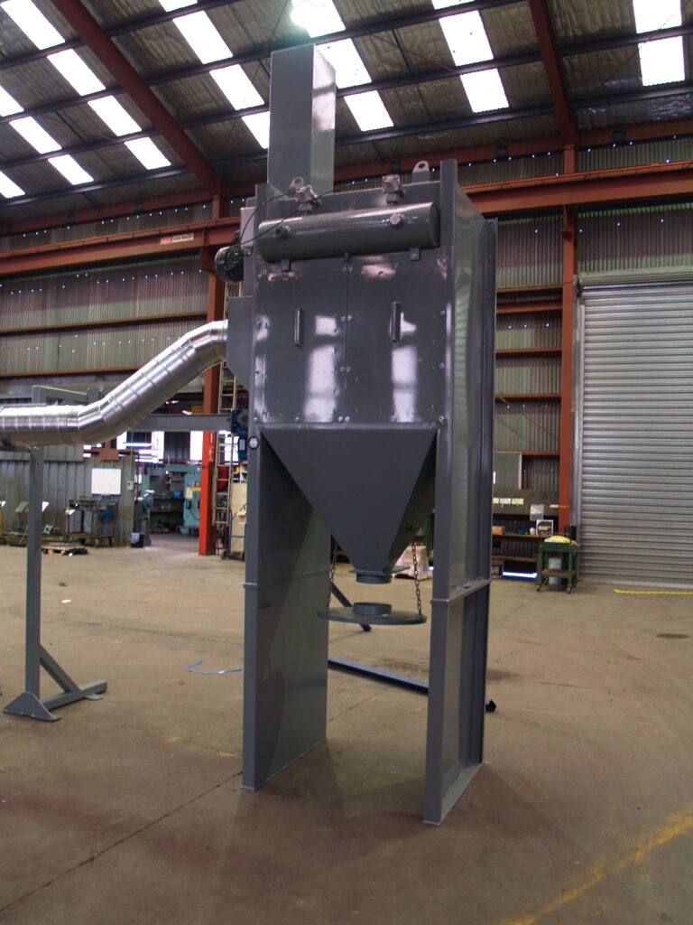
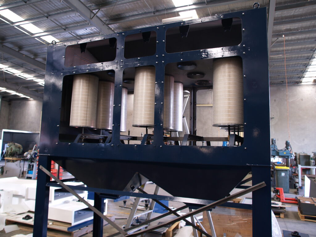
There are lots of variations but the most common basic design has a lower chamber where the air enters and passes through the filters which are mounted on a horizontal plate. Above this horizontal plate are the reverse pulse cleaning components (more on those later) and the outlet where a fan is typically mounted. Below is an image of a partially assembled dust collector where you can see some of these components.
Calculation
Requirements
Assuming you need to specify or validate a dust collector design, you need to do some calculations to determine:
- What kind of fan/blower you need to drive it
- What/how many filters you need to deal with that air flow
- What reverse pulse system components you need in order to keep the filters clean.
To do this, you need to know your air flow requirements and the routing path of your ductwork. I can’t help you with these two things so they will be outside the scope of this article.
Velocity
First, you need to find out how fast you want the air flowing through your air ducts. This is driven by the nature of the dust you are building the collector for and what you are trying to do. Usually, you want to keep the air moving fast enough that the dust doesn’t settle out of it and sit in the duct. This is typically called transport velocity or carrying velocity and there are tables for this- here’s an example from engineering toolbox. Now knowing your flow and velocity, you divide the former by the latter and this tells you the cross sectional surface are you need in your duct, from which you can find your duct diameter and round it to the nearest available size.
Pressure
Now that you have a flow rate and diameter, you can find out your pressure drop. If you aren’t too interested in the details of this, feel free to skip ahead to where I mention a slide rule. My source for the below is Munson, Young and Okiishi’s Fundamentals of fluid mechanic, 5th edition.
At any flow velocity fast enough to keep dust or particles suspended, the flow will be turbulent- you can double check that here if you like. This means that the flow can’t really be calculated exactly and anything we do will be using some kind of curve fitting equation. Fortunately, we are engineers, not scientists and therefore not bothered by this. We can use the equation:
\(\Delta p = f \frac{l}{D} \frac{\rho V^2}{2}\)
Where f is the friction factor, \(\Delta p\) is your pressure drop, l is your pipe length, D is your pipe dimension, \(\rho\) is the fluid density and V is the velocity.
The friction factor can be obtained from the Colebrook formula:
\(\frac{1}{\sqrt f} = -2 log\left(\frac{\epsilon/D}{3.7} + \frac{2.5l}{Re \sqrt f }\right)\)
where \(\epsilon\) is the roughness of the pipe wall. This formula is recursive and painful but for \(10^{-6} < \epsilon / D < 10^{-2}\) and \(5000 < Re < 10^8 \) it is close enough to:
\( f = \frac{1.325}{{ln[(\epsilon/3.7D) + (5.74/Re^{0.9} )]}^2}\)
which is much more wieldy. The above assumption is valid for pretty much anything involving air and sensibly constructed pipes. Another alternative is to use a Moody chart.
Now that you know how to calculate pressure drop over a length of pipe, we just need to apply some fudge factors for things like elbows, tee’s and the like. This is done by simply pulling values for equivalent length from a table and adding that to your overall length before calculating.
Donaldson Torit have automated these calculations in a cool little slide rule. This is a great tool for quickly running through the calcs though I personally prefer using equations in excel so I can save a copy to refer to later.
Now you have a flow rate and pressure drop, you need to look at some fan curves to select a fan. These will come from your supplier- They are unique to each fan. With that out of the way, we can look at…
A few practical design points
Filters
Older dust collectors used flexible socks that were mechanically shaken to get the dust to drop off. It’s an outdated way and not so good because the amount of filter surface area is pretty low for their size. These days, everyone uses pleated cartridges and reverse pulse cleaning. Pleated cartridges have so much surface area compared to socks that I always have to triple check my calculations. Donaldson Torit are the gold standard here but in some cases, for a non-special application, you can get away with basic air filters from Repco. Instead of mechanical shaking, we use compressed air to keep them clean.
Assuming that you’re going down the more reputable path, the filter supplier should be able to tell you either the maximum recommended air flow rate for the cartridge or the filter area and maximum velocity. This will tell you how many cartridges you need for your air flow.
Once the cartridges have been operating for a while, they clog a bit and the pressure drop across them increases and so air flow decreases. This is normal. If you have a small amount of dust under these conditions, the high velocity crams the dust hard into the cartridge and it doesn’t come out in pulsing. That’s not good. For this reason, suppliers recommend that you choke down the air flow for this run in period. An old trick I have heard of but not tried is “seasoning: the cartridges with French chalk so that you don’t need to readjust them after run in (or figure out just how long a run in takes). Also, they strongly recommend against changing just one filter in a bank. They should all be changed at once.
The reverse pulse system
In order to get the dust to drop off the cartridge and fall down to the hopper, we vent a quick pulse of compressed air backwards through the filter. How much? It’s very complicated and also very simple. The simple answer is that there needs to be just slightly more airflow backwards than there is forwards in order to allow the dust to fall and not get sucked right back into the filter. The complication is in figuring out what combination of valve and nozzle will do that. Fortunately, since this is a common thing to be doing, there are lots of off the shelf solutions. Most people use Pentair/Goyen components and their sales team have a good calculator so best bet if you’re new at this is to call them and ask.
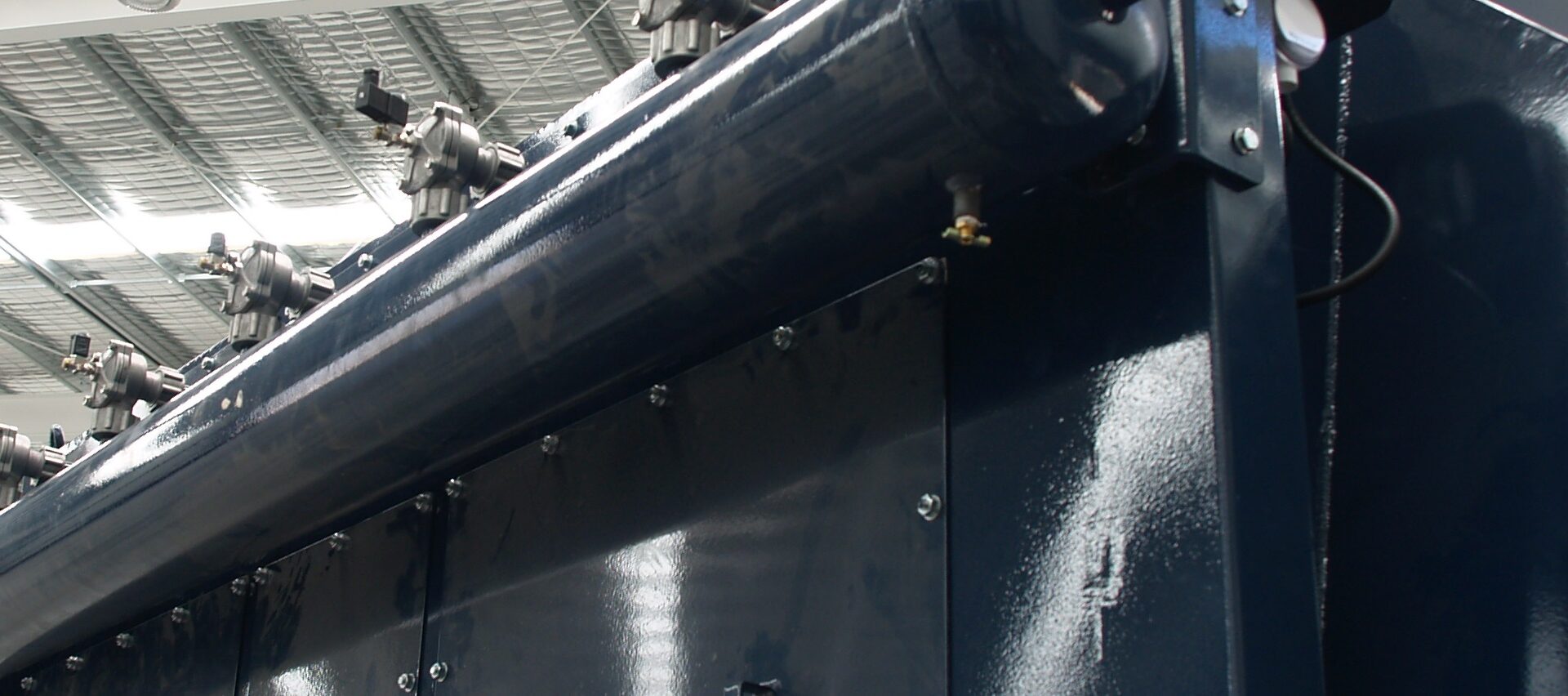
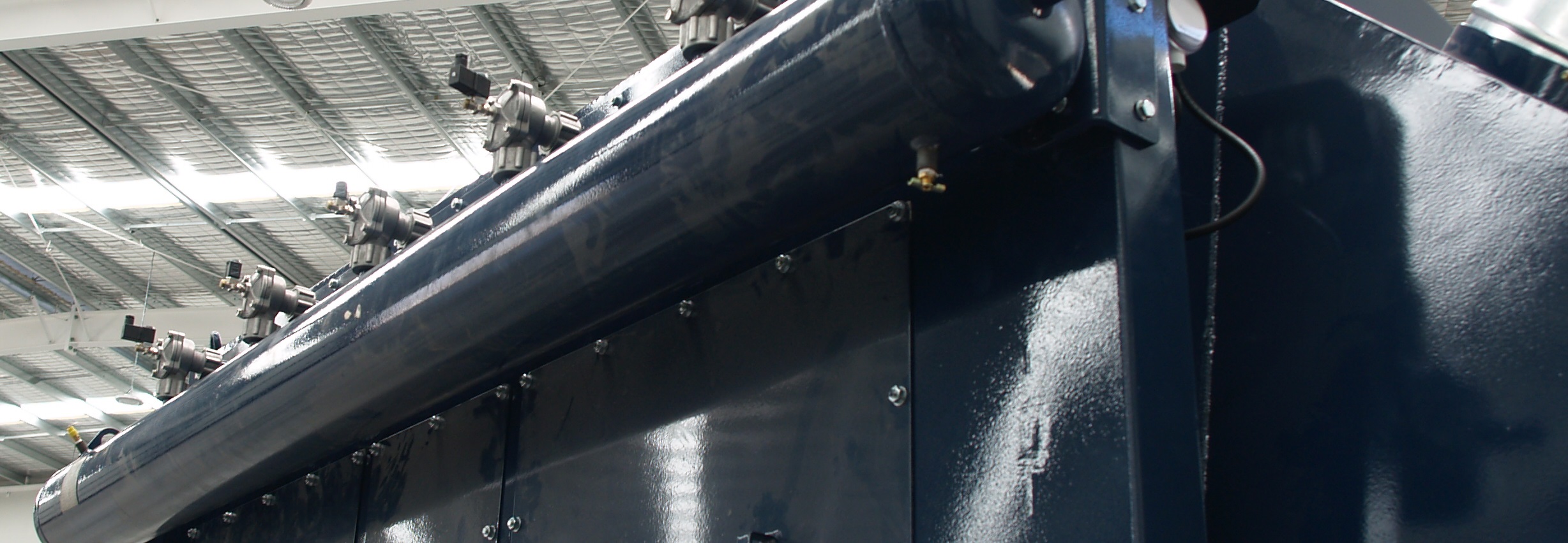
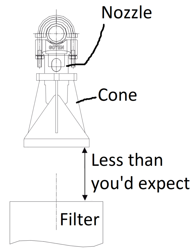
The standard pulse valve system is generally a pressure vessel on the side of the dust collector with a pulse valve venting through a drilled pipe above the cartridges. A nozzle is attached to the pipe. The nozzle comes with an attached cone which entrains free air in order to maximise the amount of backwards flow for each pulse.
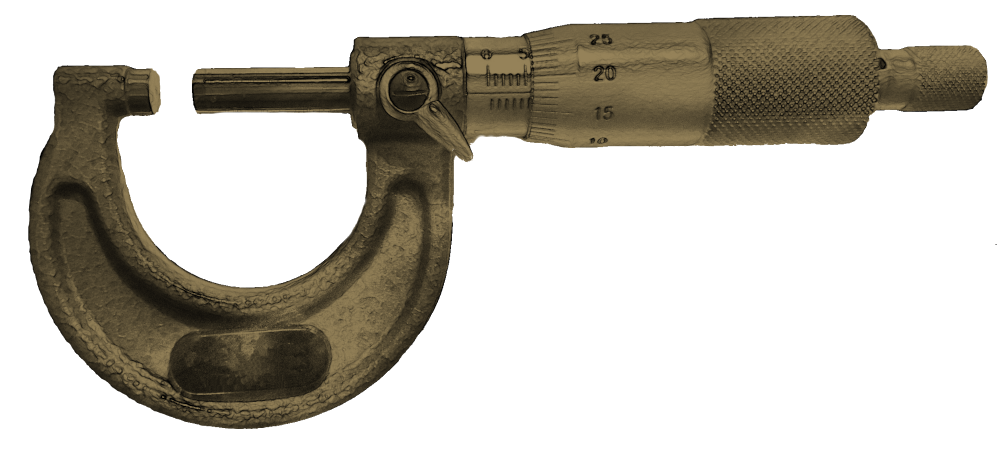
Pulse valves
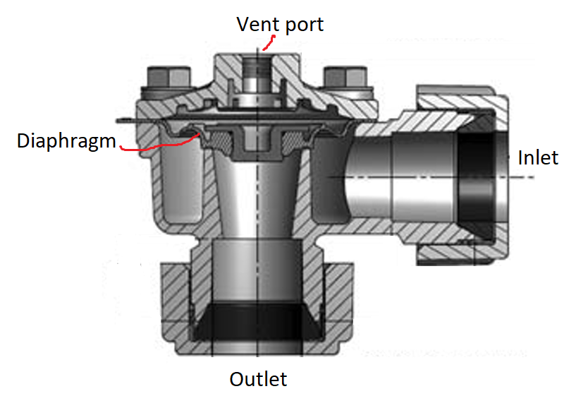
The valves we use for this are specific for the application and are known as pulse valves. They operate using a diaphragm with a small hole in it- see the picture below. The air comes in at high pressure at the inlet. The outlet is at low pressure and the vent port is nominally closed. There is a small hole in the diaphragm that allows air to bleed past it from the high pressure side to the area where the vent port is. This equalises the pressure on both sides of the diaphragm and since there’s more area on the vent port side, as well as some residual spring pressure deigned into it, this seals the diaphragm over the outlet port. When you want to activate the valve, you vent the vent port to atmosphere. Now since all the pressure is on the inlet side, the diaphragm is pushed out of the way and the air flows quickly from the inlet to the outlet until such time as you close the vent port. This all happens in a fraction of a second.
There are certain conditions under which the diaphragm doesn’t snap shut but rather flutters and this causes premature failure of the diaphragm. It sounds like a buzz or a brrrrt at the end of the pulse. It’s usually caused by a lack of pressure in the high pressure side of the valve. This in turn can be caused by the pressure vessel being to small, the air supply being undersized, too long a pulse. There are also cases where harmonics can come into play and cause this, things to look out for here are the inlet to the pressure vessel pointing at the inlet to the pulse valve or having multiple pressure vessels connected to each other with a large pipe. Weird corner cases aside, I’ve found that these pulse valves are usually very reliable though you do have to replace the diaphragms from time to time.
Mac valves make an alternative to the diaphragm pulse valve that I haven’t tried but definitely would if I had this issue.
Controlling the pulse valves
This can be done with a standalone controller, which is a very old but reliable piece of tech or by driving them yourself with solenoids and your PLC. The advantage of controlling them from your PLC is that you can do some trickier things such as vary pulse duration based on pressure drop across the filters or shut off the fan before pulsing so that you don’t need to use so much compressed air to pulse clean the filters. You might also be tempted to think that it’ll be cheaper than the rather expensive pulse controller but once you add in the cost of the solenoid valves, you don’t save much money.
Pressure vessel regulation
I don’t want to turn this article into a full breakdown of the standards so the following is a very rough guideline only! Since you will likely have a pressure vessel to run the reverse pulse system, you need to conform to AS/NZS 1210. This standard is currently over 400 pages long and covers everything up to giant boilers full of explosive, toxic gas- most of it doesn’t apply to our application.
Your goal should be to design your pressure vessel such that it is hazard level E according to AS NZS 4343. If you keep your design stress under 50MPa, this is pretty easy to do. If you are hazard level E, the things that you need to do to keep AS1210 happy are minimal. You need to do your hoop stress and longitudinal stress calcs, have corrosion allowance, hydrostat test it, mark it and have a pressure relief valve.
Conclusion
You should now know enough about dust collectors to get yourself in trouble, which is a good place for an engineer to start. Remember to keep your calculations conservative and where pressure vessels are concerned, if you aren’t 100% sure what you are doing, get help. Have fun designing and change all your cartridges at once.
1 thought on “Dust collector design”