More design tips
Adding to my previous article, here’s a few more tips and tricks for the designer.
Simple calculations are perfectly fine most of the time
Finite Element Analysis is now included in the base of many CAD systems- at least a pared down version. It’s a fantastic tool for fine tuning and validating your design. It also lowers the bar of applicability and has opened up some new pitfalls for a junior engineer to fall into. One is over-analysis where you spend three days trying to get your design to mesh correctly when you could have just used a simply supported beam equation. The other is mistaking a complex but low quality analysis as being superior to a simple but well defined one. It goes something like this- “Fix, fix, mesh, load, COLOURS, FABRICATE!”
As a general rule, your time is expensive and steel is cheap so if weight isn’t severely detrimental to your design, a good approach may be to just make pessimistic assumptions until you can calculate it and then calculate it. As an example of this, I once was making a circular mounting fixture that had a load in the middle and was supported on the four compass points of the circle. Time and money were very important, mass less so. The rough design I was thinking of using was a big circle with a cross in the middle of it. From there, I’d add mounting points and figure out the rest as I went along. I puzzled over it for a while, thinking about how to do a deflection calculation on a situation like that before deciding to just consider two of the compass points and the load in the middle, not think too much about everything else and the problem effectively became a simply supported beam equation. A quick calculation in excel told me that the minimum steel thickness was less than I wanted to use anyway so off I went.
Bend reliefs from CAD are terrible
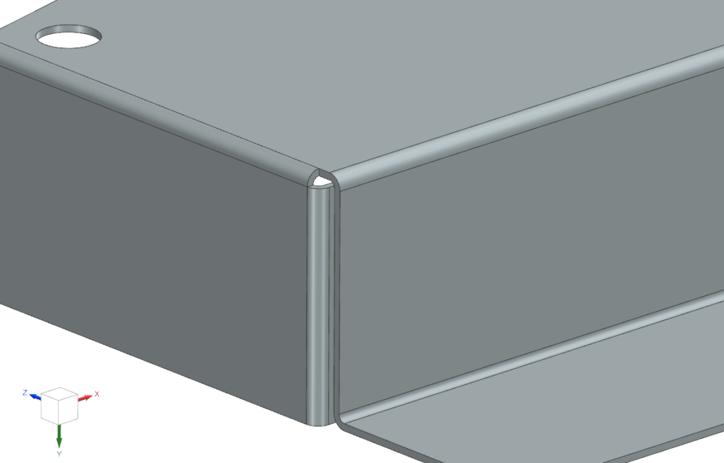
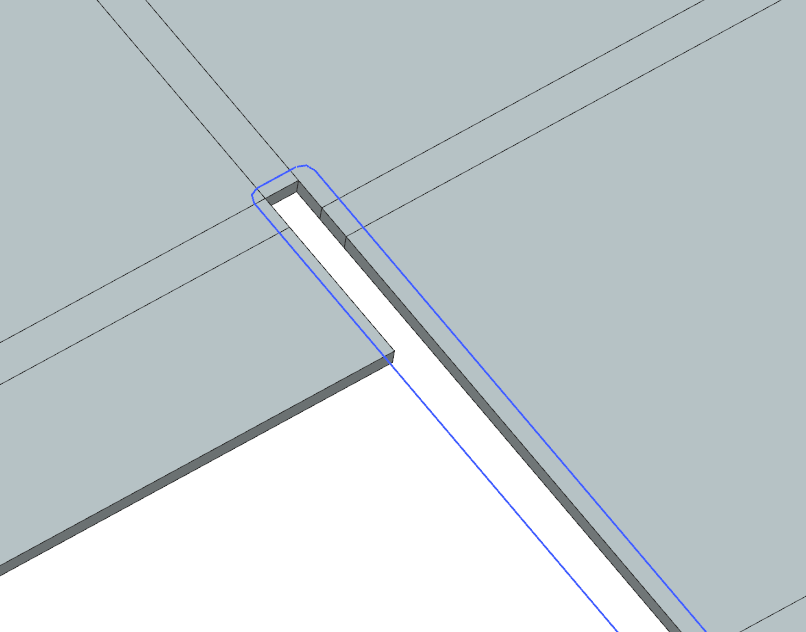
I keep hoping that I’m wrong about this but every time I try, I just can’t get a decent bend relief out of any CAD package that I use. They are all terrible! If you are designing a mild steel cover that’s going to get the corner holes MIG welded up then fine, no dramas. But I’ve also had to design aluminium structures that were designed to be riveted and exposed to vibration loads and standard bend reliefs are not suitable for this. See the image below for some detail- These reliefs are a major stress concentration and will likely crack.
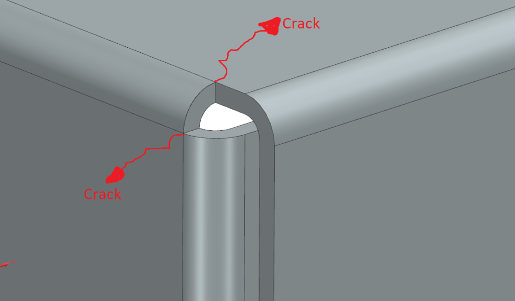
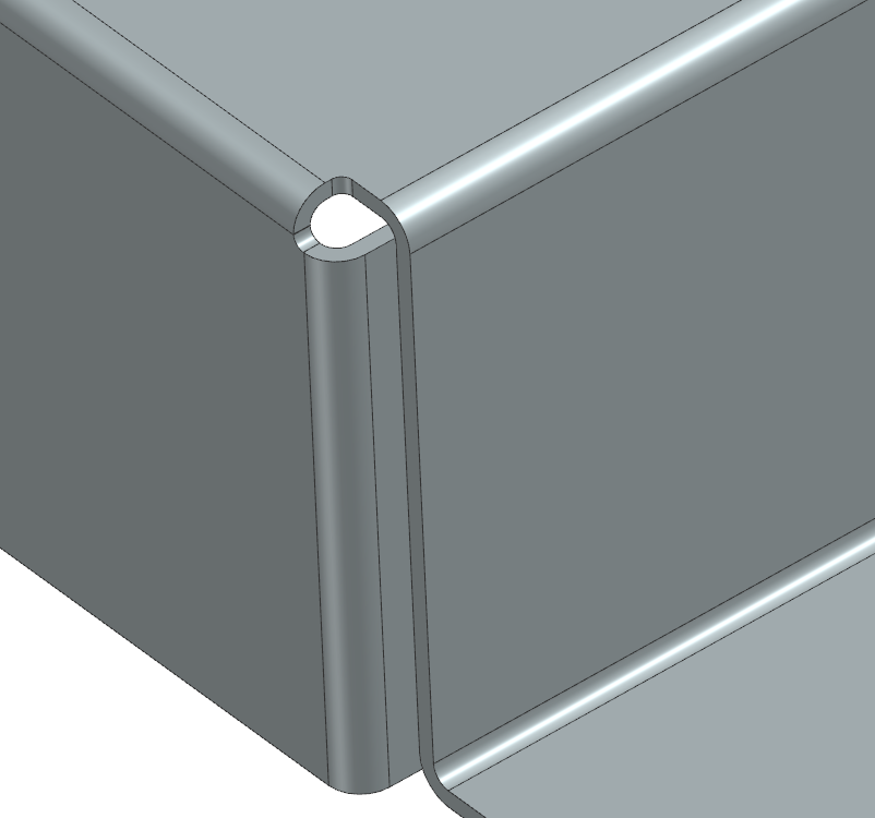
My solution is shown below and unfortunately it’s quite time consuming- The only way I’ve learned to do this properly is to unbent the part, draw in my own bend relief and re-bend them. If possible, I’ll have an internal corner radius about the same as the material thickness.
CAD, defaults and templates
When working with CAD, if knowing the mass of your final assembly to any degree of accuracy is important, I’ve found it best practice to set the default material density to something stupidly heavy (like several orders of magnitude denser than steel). This will make it very obvious if you haven’t properly allocated your materials. If you don’t do this, the habit of leaving things as “default” material will start to catch you out as your model becomes more complex. Sure, most of your parts may be either mild or stainless steel but as you use imported CAD models for things like pillow blocks and electrical cabinets, the exceptions start to compound and you end up with an inaccurate idea of what your system weighs.
On a similar vein, if you need to be careful with your materials- like 304 stainless vs. 316 stainless vs. duplex for environmental reasons, you should play with your default material colours. They are typically all shades of grey or silver that hard to distinguish at a glance. I prefer to have an obvious colour tinge to them to avoid making mistakes. Something like green for 304, blue for 316, red for carbon steel or something like that.
One more- make use of template parts! Make a few similar machines and you’ll find that every day, you model up 4-hole mount plates, 2-circlip machine pins, 1-fold angle brackets and so on. Save some templates for this stuff.
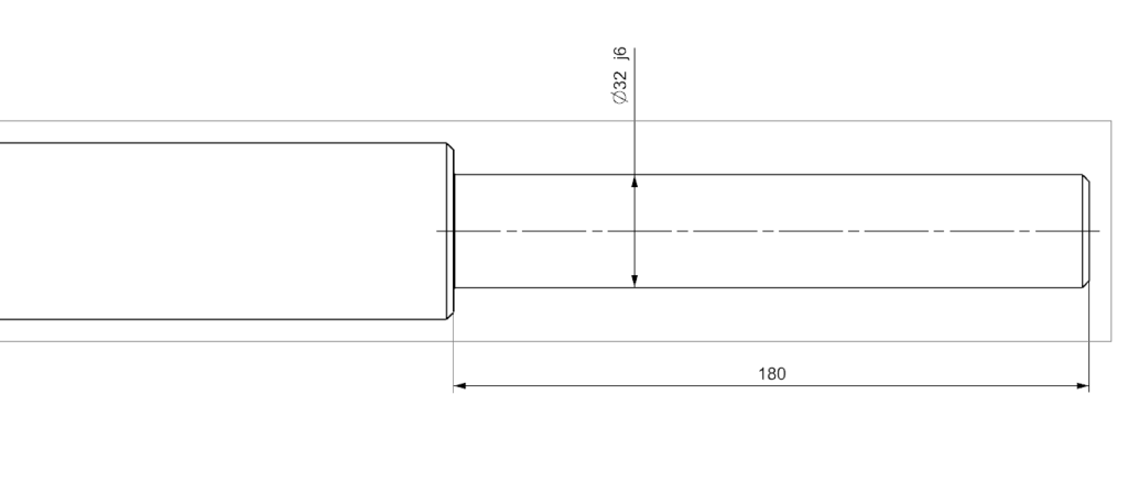
Don’t make really long bearing seats
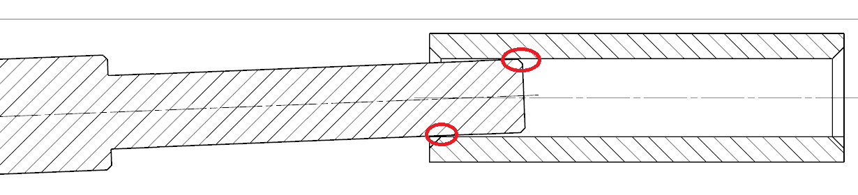
It’s very common to have two bearings on a shaft with the same fit and therefore the same diameter. Don’t fall into the trap of having a single, long bearing seat as shown in the below picture. This is for two reasons. Firstly, the longer a feature is, the harder it is to hold tolerance on it. If a machinist is paying attention, he’ll quote a higher price because he knows it may cause problems. The second reason is that it’s harder to install and remove bearings. Imaging setting up an arbour press for it. You set up the shaft on the anvil and find the longest cylinder you can fit in the press and press the bearing down until you run out of travel on the press. Then you do it again a couple more times before you actually get the bearing where it needs to be. Removal is even worse as you have to remove extensions from the puller and wind until you’re out of travel again and again… painful!
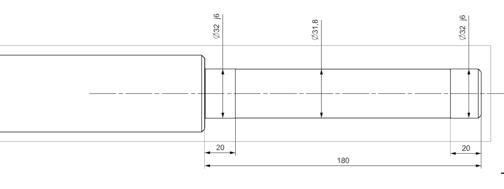
It’s much better to have a smaller diameter relief between them as shown below. Holding tolerance on these two bearing seats is trivially easy, even on a clapped-out old lathe. In our arbour press thought experiment, you only have to press the bearing down a little bit before it comes free and falls to the bottom seat area and you then only need to change your press tool once. Removal is also much easier. You only need to change your puller setup once to get it off.
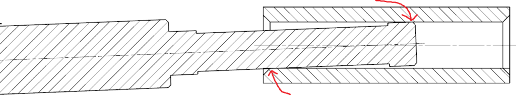
Here’s a similar issue- long shafts in housings. If you have a real good read of your gearmotor supplier manual, they will give you a similar suggestion. When you’re inserting a shaft into a sleeve, particularly as the diameters increase, it can get quite tricky to get them square. They love to bind up on the corners before you get them “started.” See the image below. It’s drawn with an exaggerated clearance and angle to make it easier to see.

Now here’s an example with a generous relief drawn in. You can get the shaft most of the way through before the corners touch. Now the sleeve can apply much more of a moment on the shaft to help “guide” you in, hopefully now without binding. It makes for a much easier install.
Extracting faces to sheet metal
This little trick is something that you may have already run into in a CAD tutorial but I didn’t know it when I started off and it’s valuable enough to warrant inclusion here. When you are making things like hoppers and other complex sheet metal shapes that need to fit together, it’s tempting to use the work flow that you first learn with sheet metal which is making bends and flanges and then spending ages fine tuning angles, trying to make them all fit together. The better way is to make a solid that represents the overall shape and then convert the surfaces of that solid to sheet metal. Depending on the CAD system, it’s called “sheet metal from solid,” “extract faces” or something like that but they all have it and it’s priceless.
There are lots of advantages to this method. particularly, you can constrain them all together by the origins instead of using other constraints. Another is that they always fit perfectly together.
Painted or galvanised mild steel or stainless steel?
Some projects are a scale where you can simply make everything out of mild steel and powdercoat or paint it. That’s nice and simple-protect the threads and/or chase them quickly with a tap in a hand drill afterwards. Sometimes it’s not so clear cut. On a small (say smaller than an a4 sheet of paper) laser cut and/or folded component with no welding, it may be worth considering just making it out of stainless so it doesn’t need any surface coating or thread chasing. The difference in material cost isn’t that much, especially if we’re talking about a sheet metal cover plate.
On installations outside or in harsh environments, you may need to galvanise them. This means that any large threaded holes need to be drilled smaller then pilot size and then subsequently drilled out and then tapped after galvanising. Small holes can only be drilled and tapped afterwards. The hot dip process seems to slightly harden the steel 1-2mm deep which makes this an irritating procedure. This lowers the threshold for using stainless steel as all that post work may well cost more than just using stainless steel.
That’s all for now- Happy designing!