Designing for gas struts
Introduction
Gas struts are a great element to add to your machine design but can be tricky to get right, especially the first time. In this article, I’ll cover some basic principles of how gas struts work and then how to do design calculations on a gas strut system that is lifting a hatch that swings up vertically using some high school math and excel. Then I’ll cover some practical design considerations.
Reading my charts
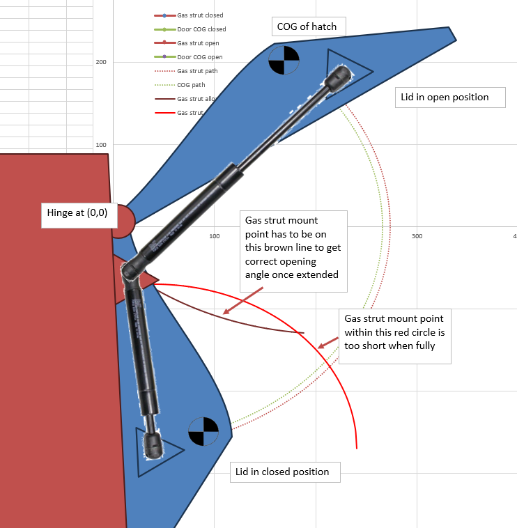
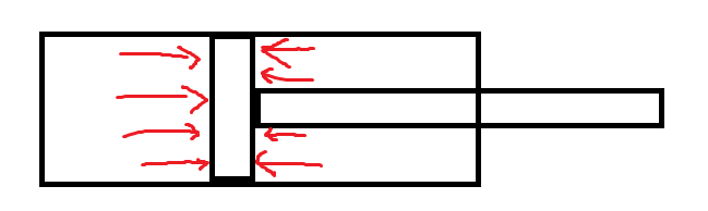
First, let’s get familiar with how I visualise the geometry. For this example, I’m using a hatch that opens upwards from something close to vertical through 120 degrees of movement, ending up overhead of the user. This system is using a single gas strut. Designing for two is more common and can simply be done by doubling the gas strut force in the calculation.
I sketch this up using a scatterplot so I can get realtime feedback on the geometry I’m entering into excel. This means I don’t need to go back and forth with CAD to sort out my plan. I’ve overlaid some graphics to make it easier to understand it.
Note the hinge point is at 0,0 as it makes calculation easier. I enter all geometry into excel assuming the lid to be closed and calculate where it moves from there. The important points are the centre of gravity and the gas strut pickup points. Where the actual door ends is not really of concern. I have a collection of standard gas struts loaded into a list on my spreadsheet that I can select from. I assume that the gas strut will be limiting the travel- this means that if I define where the pickup point on the door is, then the position of the “ground” side pickup point is defined by a circle where the radius is the extended length of the gas strut. This is shown in brown, below. Also, the minimum length of the gas strut is also defined- This is shown by the red circle. If we place the ground side pickup point in that circle, we won’t be able to close the lid because the gas strut will bottom out.
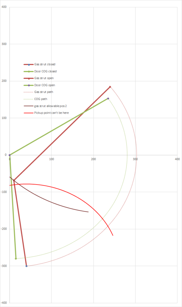
Now here’s the actual scatterplot that I use without the autoshapes:
What do we want?
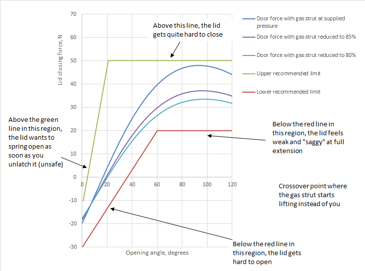
Now, before we get into calculation, we need to know what we want to achieve. See the plot below of net force at the door tip or handle vs opening angle. This shows us how much force the user needs to apply to the lid in order to open it. There’s a few important features on this graph. Firstly, at low opening angles, you want the lid to be self closing. This is because when you have gas struts, a lid that isn’t self closing is self opening. It may not seem like a big deal but opening a hatch or door like this is scary and potentially dangerous. If you aren’t expecting it, you can cop a door in the face when you unlatch it.
Secondly, you may note that the force curves all cross over the zero point at about twenty degrees. This crossover point defines where the gas strut “takes over” from the user. You want to keep this fairly low as the higher the hatch gets, the harder it is to lift it.
Finally, you’ll note that all of the force curves peak and taper off at a point. This generally happens regardless of how much you play around with geometry and it’s fine as long as it doesn’t taper off too much. If you let it taper a lot, you’ll get a hatch that feels OK while opening it but is weak and saggy at the top position which doesn’t inspire confidence.
Finally, take into consideration the limitations of this model- We’re ignoring:
- Hysteresis due to friction within the gas strut
- Inaccuracy in fabrication
- Inaccuracy in our estimation of the mass of the hatch
For this reason, we need to play it safe- It’s generally better to have too strong a gas strut as they can relatively easily be reduced in force but not increased.
How a gas strut works
Gas struts are quite clever. They are basically a piston in a tube like a pneumatic cylinder- however, there’s a hole in the piston that lets gas apply pressure to both sides of it. Because one side has the rod and the other side doesn’t, there’s more area on the non-rod side for the gas to apply pressure to, so there’s a net force in the extending direction.
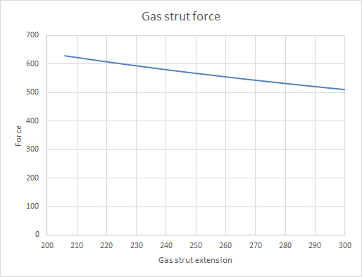
Suppliers spec these pretty simply- They tell you what the force is, which is close enough to linear most of the time but since we’re making a calculation spreadsheet, we can go into more detail on that. The reason why the are slight nonlinear is that as they are retracted, the rod takes up space and since the overall volume in the strut decreases, the pressure increases. We can model this using the ideal gas law
So, for example, a gas strut has a tube diameter of 18mm and a rod diameter of 8mm and a quoted force of 637.65 Newtons, which I’ll assume is at full retraction. We can figure out the internal pressure from this-
\(Pressure = \frac{Force}{Area}\)
so
\(Pressure = \frac{637.65}{\pi \cdot 4^2}\)
Remember that gas struts have pressure on both sides of the piston and the difference in area from one side to the other is the cross sectional area of the 8mm rod. Also note, if I use Newtons, Milimeters and Megapascals for everything, I won’t need to do any unit conversions.
So our pressure is about 12.69mpa. Now I can use my ideal gas law equation to know what the pressure is at some condition of extension.
\(p_1\cdot v_1=p_2\cdot v_2\)
Rearranging and instead of p1, p2, v1, v2, we’ll call them pret, vret, pext and vext for clarity.-
\(p_{ext} = \frac{(p_{ret} \cdot v_{ret})}{v_{ext}}\)
Let’s call the gas strut tube volume at full retraction vret, the cross sectional area of the rod arod and the amount of retraction of the gas strut dret
\(p_{ext} = \frac{p_{ret} \cdot (v_{ext} – a_{rod} \cdot d_ {ret})}{v_{ext}}\)
Continuing the above example, at a retraction of 100mm,
\(p_{ext} = \frac{12.69 \cdot (25447 – 50.27 \cdot 100)}{25447} = 10.18mpa\)
Now I can roughly model the gas strut force as a function of retraction, even though it wasn’t included in the spec sheet. Nice.
Calculating gas strut/hatch system
We are considering two forces- One is the weight force of the door which is always downwards. This creates a moment about the hinge that is easy to calculate- it’s just the weight force times the cosine of the x coordinate of the centre of gravity, since we are assuming the hinge to be at (0,0).
The second force is that of the gas strut, which creates a moment about the hinge point at (0,0). You may recall that this can be calculated by the cross product of the gas strut force vector (we’ll call that F) with the vector of the gas strut pickup point (we’ll call that p). If we call the angle from one to the other \(\theta\), this can be described as:
\( ||F|| \ ||P|| \cdot Sin( \theta )\)
Don’t be distracted by the mathematical notation- This is simply the absolute value of the gas strut force vector (ie, the gas strut force we already calculated), the absolute value of the gas strut pickup vector (ie the distance between the origin and the gas strut pickup point) and the Sine of the angle between the two. It’s deceptively simple. The only trick is to be careful with your +/- signs so that your torques are all in the correct direction.
The overall torque on the door is simply the sum of the torque due to weight and the torque due to the gas strut. In order to calculate the force that the user feels when lifting the hatch, just divide the overall torque by the distance from the hinge to the handle.
Now we have the formulae set up, we can put something together using Excel. I’ve put in a screenshot of how I did it, along with my setup parameters so you can check your numbers against mine.
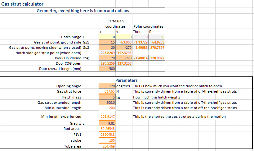
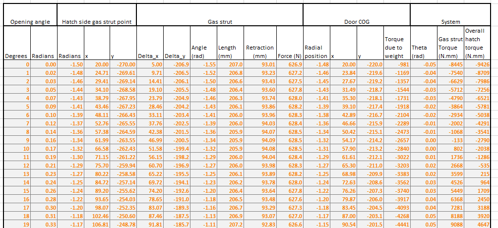
A couple of notes on the above- In order to simulate the motion of the hatch opening, I simply converted the Cartesian coordinates to polar, and rotated everything by one degree increments. This sounds more complicated than it is. It’s simply a matter of finding the angle (=ATAN2(x, y)) and radius (=SQRT(x^2,y^2) of the points from the origin, adding a degree, and then converting back to x and y coordinates (=r*cos(\(\theta\)) and =r*sin(\(\theta\)) respectively).
As a final point on calculation, don’t forget to check it! Some good ways to do this are to override your gas strut force to a big round number, set your hatch weight to the same number, change the position of the gas strut so it’s vertical when the door is horizontal and see if the forces cancel to zero in that condition. See what happens if your gas strut is pointed directly at the hinge (zero torque) and the hatch weight is zero (should be zero resultant torque). Check that the torque from the gas strut reverses sign when the gas strut is pointed at one side of the hinge versus the other. Things like that. Also, start small. Have a fixed gas strut force and get that working before you model the force reduction.
If you want to go a step further, try modelling the internal friction of the gas strut so you can see the difference in user force opening vs closing the hatch.
Practical considerations
Geometry aside, there’s still a few things to look out for when designing gas struts
- Gas struts are filled with gas and a small amount of lubricant. The lubricant is for the seal around the rod. For this reason, it’s best to mount them so the lubricant can do this job. In the case of our hatch, assuming that it spends most of its time closed, that means the rod at the bottom and the cylinder at the top. That way, the lubricant will settle down the bottom at the rod seal and lubricate it as it extends.
- If your hatch is likely to be flimsy, two gas struts is better than one or you’ll get unsightly twisting.
- As mentioned above, hatches that are self opening are not great and in extreme cases, they can be unsafe. They can also have sealing issues if your latch isn’t tight.
- Adjustable gas struts are common but note that they are typically supplied at full pressure and the adjustment involves reducing that pressure. So if in doubt, go stiff and reduce pressure from there.
- Manufacturing tolerances are always there and we haven’t accounted for hysteresis in our calcs and sometimes we just make mistakes- so even after all this planning, if you’re laser cutting your pickup points, a couple of extra holes is free. You can tell your customers that in twenty years time when the gas strut pressure has dropped, they can use the alternate pickup points. You weren’t planning for a mistake, you were planning for extremely long service life. The gas struts on the hood of a Z31 Nissan 300zx had pickup points like this.
- Having a hatch or lid that opens one degree less than design is no big deal. Having one that closes one degree less than designed is a very big deal. It’s better to lose a couple of degrees of opening in order to ensure it will fully close so don’t make the gas strut fully retracted in the closed position. Give it a few millimeters to breathe.
- If your gas strut is saggy at the top and you are unable to fix that, consider using a locking tube for a bit of extra safety.
Hopefully after all this you were able to follow along, you have your own calculation spreadsheet and you can start designing your gas struts with confidence. Have fun and may your lid never be saggy.