Design tips
As an engineer that is not tied to any particular industry, I’ve come across a pretty wide variety of equipment, problems and environments and they all come with their tricks and traps. Here’s a few random design tips that I’ve picked up over the years- I hope you find them useful.
Section views convey more information than exploded views
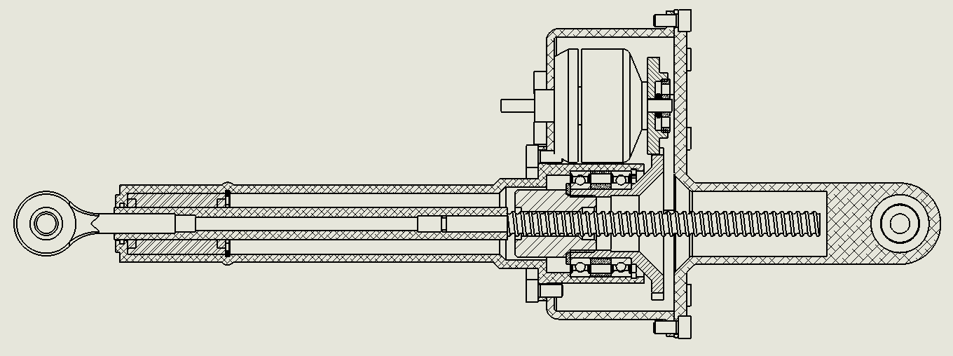
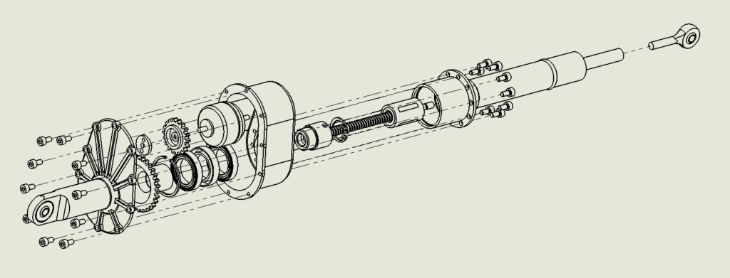
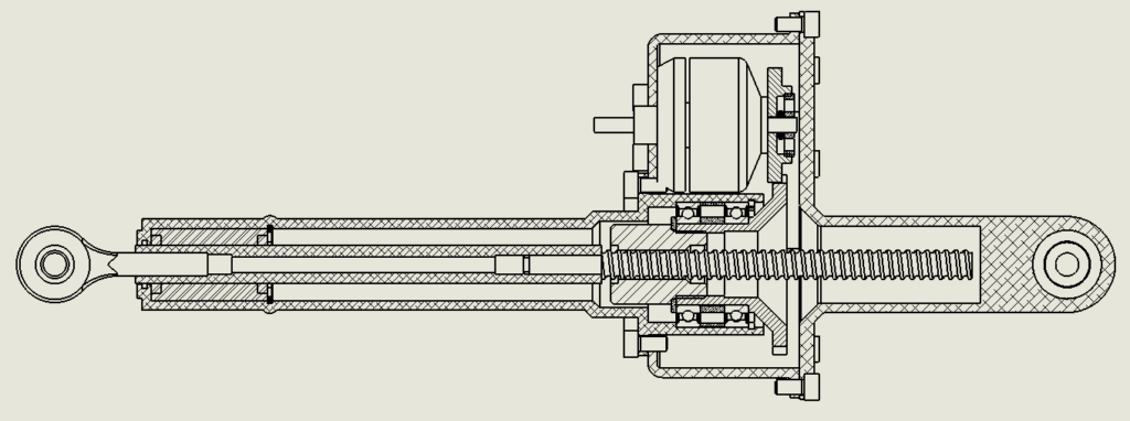
Exploded views are easy to understand and have their use but if the intended audience of the drawing is from a skilled background, I prefer section views. Where an exploded view explains assembly order, a skilled eye can infer this from a well constructed section view as well as the as-installed condition, where the clearances are and how things are retained.
An example is shown below. The exploded view shows assembly order but with the section view, you can look at the ball bearing arrangement on the lower gear and see how it is axially located. You can see that the upper and lower gears are not quite axially aligned. You can check that the bolts holding the cover plate on are long enough (perhaps too long) and that the machinist is going to have a hard time cutting the internal circlip groove in the tubular housing and the assembler is going to have an even harder timing installing said cirlip.
Nobody said you can’t have both types of view on your drawing but you need to choose where your time is most effectively spent.
Manufacturers are conservative with their tolerancing as they assume worst case applications
For example, if you’re using a pair of pillow blocks to mount a shaft that’s only going to be used as a service door hinge, you don’t have to machine a js6 tolerance bearing seat. Use h9 bright steel, just throw it through, it’s fine. It’s not a machine spindle, so don’t overcook it. Similarly, gearmotors are spec’d quite tight fits on shafts because with load reversals, lots of stop-starts or high loading, clearance results in fretting, keyway wear and ultimately, compliance between the motor and shaft which is typically a bad thing. However, if the application is a slow turning screw conveyor that doesn’t stop-start very much, it’s unlikely that you’ll see this type of failure before the flights of the screw conveyor wear away, in which case, it may be better to have a looser fit so the gearmotor doesn’t require a puller to be removed.
On fasteners
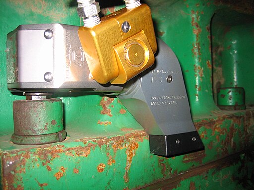
There is a huge cost spike for bolts at about M20 size. If you can keep it under M16 you definitely should. If you are designing for large fasteners and tension isn’t critical, reconsider why you are using such large fasteners. If tension is critical, you need to think about how you are actually going to properly tension them. As your bolt size gets even larger (M24+), you’ll at some point need to start using a hydraulic wrench to tension them and you need to react the torque against something while doing so- see the image below. The black part at the bottom will push against the side of this large casting while the wrench tightens the bolt. If the side of that casting there isn’t relatively square to the bolt head, instead of tightening, it just pops off the bolt.
Most of the cost of bending is setup
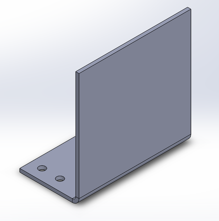
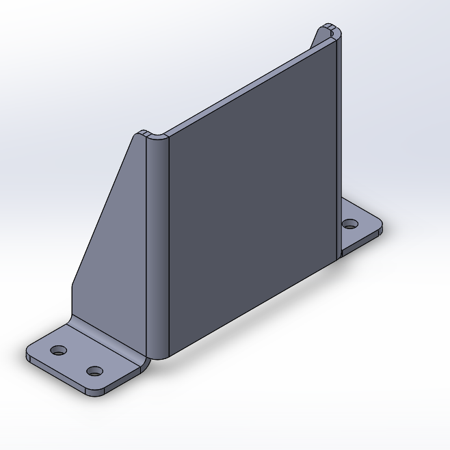
As soon as you have a bend on your part, its cost has increased significantly. Assuming you are outsourcing this bending to a supplier that uses a CNC brake press, adding one or two more bends to it often doesn’t increase it much more- The majority of the cost is in setup. So with that said, say you are making an end stop. You might design that to be a single 90 degree bend with holes on one side like the image on the left below. If having a relatively compliant part is what you’re after then this is fine- But if you want a bit more stiffness, add two more bends and make it like shown on the right. Now it has two shear planes resisting the load, making it far stiffer.
Don’t spec a threaded hole full depth
The machinist making your part doesn’t know the application of your part. Maybe the part was drawn that way because the threaded depth was calculated based on minimum pullout force and also the part carries a bending load so the hole depth was minimised for strength. Maybe you just let CAD make a “full depth” thread by default. There is no way for them to tell. The result is that the machinist will tap the hole full depth with a conventional tap. Then tap it full depth with a plug tap. Then they’ll blow out the swarf with compressed air and run in the plug tap again. Then they’ll charge you for all that time. Or if they are running a CNC machine, they’ll smash 3 taps trying to get the depth and make a mental note to charge you more next time.
Steel rule dies are great
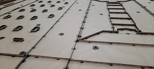
A common requirement in machine design is soft seals, padding, lining and gaskets. In the past, I used to have these supplied waterjet or even hand-cut. The idea of making a dedicated cutting die for anything always seemed out of budget for anything I was working on. At some point, I stumbled upon a company called Fine Formes who manufacture steel rule dies- and they are amazingly cheap! They simply use a CNC flat wire bender to bend the steel rule and a 2 axis router to rout out a holder from plywood and stick the two together. All they require from you is a dxf file of the profile you want cut. I’m not affiliated with them in any way- it’s just a secret worth sharing.
Avoid making-to-fit, make to spec instead
Ideally, all our parts can be made to a drawing and then assembled without issue. In reality, though, there are problems and things don’t fit together. Fabrications are particularly susceptible to this. They move around. When you encounter such a problem and are thinking about how you can avoid a recurrence you may be tempted to specify on your drawings to match-drill holes or to tack weld parts together and fabricate to fit. This is a trap to be avoided for the following reasons:
- You cannot supply replacement parts and expect them to fit
- It slows down the manufacturing process by forcing parts to be made sequentially
- Identical, symmetrical parts are no longer those things. They now only fit in one particular orientation in one particular location
- Large diameter holes in thin metal generally aren’t round and have ugly burrs from drilling
If you are having trouble trusting that the parts are going to fit together without match welding or match drilling, you have a design issue to fix. Typically this comes down to either designing the component such that a finer tolerance can be achieved or eliminating the need for finer tolerance. Here’s some ideas:
- Methods to hold finer tolerances
- Use tab-and-slot techniques on laser cut parts to reduce the dependence on measurement.
- Align-ream or align-bore holes if required.
- Design and manufacture a fixture. If you make that design again, it will be very fast to make!
- Talk to your bender and get a k factor table or a bend relief table.
- Methods to reduce the need for fine tolerances
- Use self aligning bearings if possible.
- Have key parts bolted instead of welded on so they can be assembled and torqued down in alignment.
- Ensure that your holes have proper clearance. If you need two hands to lift your part, chances are the default bolt clearance holes in CAD are too tight (even on the “loose” setting). For example, I’ll often use a 12mm hole for a 10mm bolt.
- If you have folded parts in materials thick enough that you can’t trust where things are going to end up, slot your holes.
On springs
Selecting the right force for a spring application is difficult. The spring calculation itself isn’t usually the issue; it’s that 10N in your calculation seems pretty soft until you make the assembly and find that your latch requires steel-fingered pixies to open. Or, your hatch is so heavy is just sags on its springs. Redesigning a spring to reduce stiffness is very easy- just reduce the wire diameter. Going in the other direction isn’t.
For example, let’s consider a tension spring where we want a rate of about 200 N/mm over a deflection range of at least 8mm. You decide to use a 26mm OD spring with 8mm wire diameter and a free length of 55mm and design for that. Then you find after assembly that you actually needed 300N/mm- but your assembly is constrained by maximum 26mm OD and maximum 55mm free length. You can’t use a similar spring with a larger wire diameter as that increases the stress in the spring beyond the maximum. What you need to do is increase the coil diameter and/or the free length.
To safeguard against this, when designing springs where you aren’t 100% sure of the outcome, either leave lots of room to replace with a larger spring if required or keep your stresses very low so you can increase wire diameter and keep other parameters the same.
1 thought on “Design tips”